Configuring hardware profiles
A hardware profile can be applied to a capture adapter or a capture depending on the model of your capture adapter. Hardware profiles tell a capture adapter or a capture the type of traffic to capture and how to manage that traffic. Hardware profiles can slice the packets, discard error packets, and apply an address or a port filter. Different settings can be applied per capture adapter channel as well.
IMPORTANT: All of the hardware profile settings are applied in hardware, and allow for better performance than performing these operations in software.
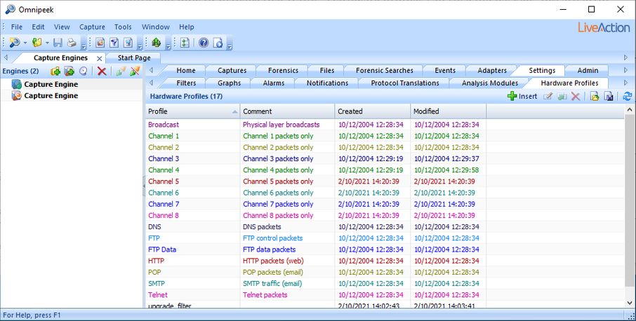
If a capture adapter that supports hardware profiles exists, the Hardware Profiles tab appears in the Settings tab.
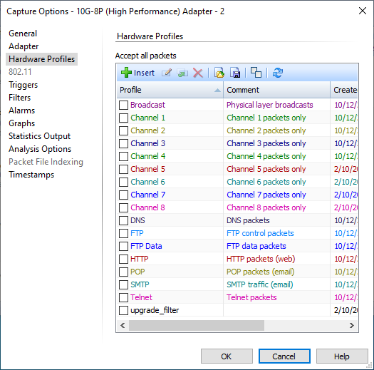
If a capture adapter supports hardware profiles per capture and is selected as the adapter for a capture in the Capture Options, then the Hardware Profiles tab is accessible in the capture options and any hardware profile selected affects just that capture.
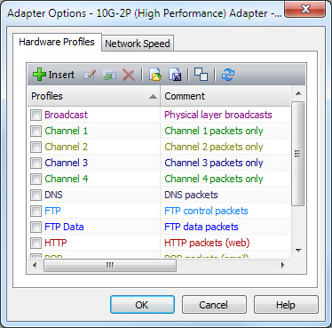
If a capture adapter supports hardware profiles per adapter, the Hardware Profiles tab appears in the Adapter Options dialog for that capture adapter and any hardware profile selected affects all captures using that capture adapter.
The hardware profile support for a capture adapter is dependent on the model of your capture adapter.
The Hardware Profiles tab allows you to define and manage your hardware profiles. In the Capture Options, the Hardware Profiles tab allows you to select one hardware profile that is used with the capture. In the Adapter Options dialog, the Hardware Profiles tab allows you to select one hardware profile that is used for all captures using that capture adapter. Packet slicing, error packet settings, and filters based on address or port are implemented on the adapter in hardware.
NOTE: Only one hardware profile can be implemented on a capture or a capture adapter at a time.
To create a new hardware profile:
1. Do one of the following to display the Hardware Profiles tab:
• Select the Hardware Profiles tab from the Settings tab of the Capture Engines window.
• Select a capture from the Captures tab of the Capture Engines window and click Capture Options for the capture. The Capture Options dialog appears.
• Select a capture adapter from the Adapters tab of the Capture Engines window and Click Options for the adapter. The Adapter Options dialog appears.
2. Click the Hardware Profiles tab.
3. Click . The Insert Hardware Profile dialog appears.
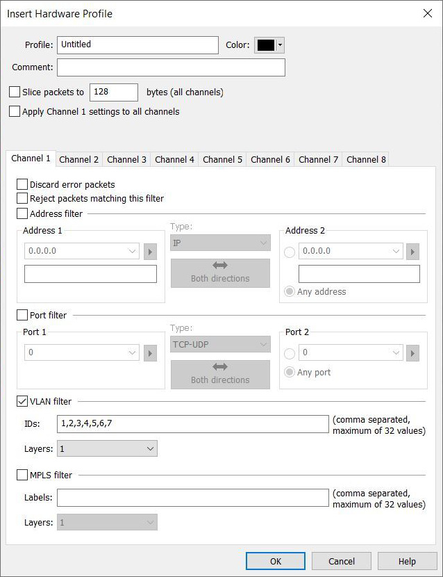
4. Complete the dialog:
IMPORTANT: Hardware profiles containing an overly complex configuration using the options specified below may result in an error dialog indicating that the hardware profile is too complex. When starting a capture, you may also get the error dialog when multiple captures use hardware profiles that are collectively too complex when used together. If you receive this error dialog, try reducing the complexity of the hardware profile. For example, try limiting the number of filters, reduce the number of channels, limit the number of VLAN IDs or MPLS labels, or limit the number of layers used in the hardware profile.
Additionally, when using multiple hardware profiles on the same capture adapter, these hardware profiles should be exclusive with each other (capturing a unique set of packets) or else you may find that some of the captures are missing packets since a packet can only be sent to one capture. When a packet matches more than one hardware profile in use, the most recent captures have precedence over less recent captures.
Additionally, when using multiple hardware profiles on the same capture adapter, these hardware profiles should be exclusive with each other (capturing a unique set of packets) or else you may find that some of the captures are missing packets since a packet can only be sent to one capture. When a packet matches more than one hardware profile in use, the most recent captures have precedence over less recent captures.
• Profile: Type a name for the profile.
• Color: Select a color for the profile.
• Comment: Type a comment to provide a more complete description of the hardware profile’s properties.
• Slice packets to … bytes (all channels): Select this option and enter a value in bytes to enable packet slicing on the card.
IMPORTANT: The minimum entry is 16 bytes, and the length must be a multiple of 16 bytes. We recommend keeping the slice value at 128 bytes or greater.
Additionally, if you have two captures on the same capture adapter, and one has a hardware profile that has Slice packets to … bytes (all channels) enabled, while the other has Slice packets to … bytes (all channels) disabled, only the last capture started receives packets while the other capture stops receiving packets.
Additionally, if you have two captures on the same capture adapter, and one has a hardware profile that has Slice packets to … bytes (all channels) enabled, while the other has Slice packets to … bytes (all channels) disabled, only the last capture started receives packets while the other capture stops receiving packets.
• Apply Channel 1 filter settings to all channels: Select this option to assign the same properties defined for Channel 1 to all channels. Clear the check box if you want to define properties separately for each channel.
• Discard duplicate packets: If your capture adapter supports this feature, this option is available and can be selected to discard duplicate packets.
IMPORTANT: If you have two captures on the same capture adapter, and one has a hardware profile that has Discard duplicate packets enabled, while the other has Discard duplicate packets disabled, only the last capture started receives packets while the other capture stops receiving packets.
• Discard error packets: Select this option to discard error packets.
• Reject packets matching this filter: Select this option to pass packets to Omnipeek that do not match this filter.
• Address filter: Select this check box to specify a filter parameter based on address.
NOTE: Wildcard addresses (or range of addresses) and CIDR range filtering are supported for Address filter.
• Address 1: Type or select the first address for the filter. Clicking the small arrow lets you select or resolve an address from the Name Table.
• Type: Select the type of addresses you want to enter. Both Address 1 and Address 2 must be of the same type and must be entered in the correct format.
Click the button with the directional arrow to select the send/receive relationship between Address 1 and Address 2.
• Address 2: Type or select the second address for the filter. Clicking the small arrow lets you select or resolve an address from the Name Table.
• Any address: Select this option to specify any address for Address 2.
• Port filter: Select this check box to specify a filter parameter based on port.
• Port 1: Type or select the first port for the filter. Clicking the small arrow lets you select a port from the Name Table.
• Type: Select the type of port you want to enter. Both Port 1 and Port 2 must be of the same type and must be entered in the correct format.
Click the button with the directional arrow to select the send/receive relationship between Port 1 and Port 2.
• Port 2: Type or select the second port for the filter. Clicking the small arrow lets you select a port from the Name Table.
• Any port: Select this option to specify any port for Port 2.
• VLAN filter: Select this option to enable VLAN filtering. This allows you to enter a comma separated list of VLAN IDs to match against.
• IDs: Type the list of VLAN IDs, separated by a comma. The list cannot exceed 32 entries and must be within the valid VLAN ID range of 0 to 0xFFF.
• Layers: Select how deep of a VLAN stack to match against, with 1 being the minimum and 2 being the maximum.
• MPLS filter: Select this option enable MPLS filtering. This allows you to enter a comma separated list of MPLS labels to match against.
• Labels: Type the list of MPLS labels, separated by a comma.The list cannot exceed 32 entries and must be within the valid MPLS Label range of 0 to 0xFFFFF.
• Layers: Select how deep of an MPLS stack to match against, with 1 being the minimum and 3 being the maximum.
5. Click to add the new hardware profile to the list of profiles.
6. Click the Click here to send changes message to send your changes to the Capture Engine.
IMPORTANT: Because the hardware profile definitions reside on a Capture Engine, you must send all changes to a Capture Engine when you use the , , , or functions.